
Published: 20 January 2021
Problem description
Since the release of PLAXIS 3D AE, tunnels can be modelled more efficiently using the 3D Tunnel designer, which reduces the need to make use of the tips discussed below. For PLAXIS 3D 2016 and later, the issue is now completely resolved by not using the internal trianglation, see the related article on Fully parametric geometry.
For older the discussed approach may still be relevant.
In the PLAXIS 3D program all geometric surfaces and the volume sides (so called BReps or Boundary Representations) are internally made up of triangles.
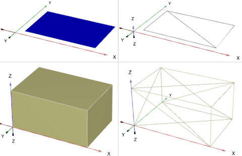
Figure 1. Rectangle and soil block and their BRep triangles (right)
Surfaces and volumes resulting from an extrusion are also made up of triangles.The extrusion tool executes the following steps:
- it will first make a copy of the shape to be extruded, and it will create a copy at the end of the extrusion vector, so called cap faces (see C in the image below)
- it will create a side surface, connecting the cap faces
- the surfaces will be combined (see D in the image below)
- and as a result we will have a new volume, that is built out of triangulated surfaces (see D and E in the image below)

Figure 2. Extrusion of a rectangular surface
As can be seen in the above example, the side of the extruded volume also consists of triangles. When the extrusion vector is very long, the side triangles will become very long as well.
When shapes like tunnels are being generated using a polycurve for the cross section and then use extrusion for the tunnel path, it will also generate these long triangles on the side surfaces (or in this case the tunnel lining):

Figure 3. Tunnel side face (top) and its BRep triangles
In itself this is not an issue, and the tunnel shape can be used without problems for intersection, mesh generation and calculation, with and without e.g. plates and interfaces.
Cutting planes
However, when cutting planes are introduced to model the staged construction of the tunnel, an issue with accuracy might occur when the tunnel shape is intersected with these cutting planes.
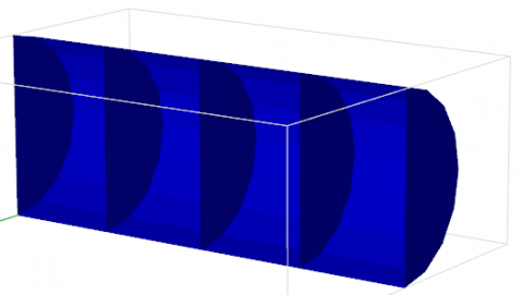
Figure 4. Tunnel with cutting planes
In order to explain what happens per triangle on those long internal (BRep) triangles on the tunnel lining, first it is shown what will happen when we intersect a part of the tunnel’s side surface with a cutting plane (represented here with a line)

Figure 5. Part of a tunnel’s side face (top) and intersected BRep triangles (bottom)
The image above shows that the contour of the long triangle is still intact and that these triangles are subdivided into several smaller triangles.
For very long triangles on such surfaces, this could lead to the generation of very small triangles for which the corner vertices are located at a distance nearing the numerical tolerance that is used in the PLAXIS 3D program. This could result in all kinds of issues when going to the mesh mode.

Figure 6. Long, narrow tunnel side face intersected with cutting plane
Solution
The problems described here are not applicable to PLAXIS 3D 2016
When an error with intersections occurs, and these do not occur without the cutting planes, these possible workarounds exist:
1. Create arrays
A simple, but convenient method to generate the desired geometry and cutting planes, is to create the first tunnel slice. Then select the tunnel slice and use the array tool to add all the sections. This will give separate objects for all sections, and can only be applied for straight tunnels.
2. Use the extrusion tool along a second polycurve
This option is available since PLAXIS 3D 2012
Instead of using an extrusion vector, a second polycurve is used as path such that it matches the excavation slices. As example we will use a straight tunnel that will have 20 cutting planes with a distance of 1 m between each of them. The second polycurve, created with the shape designer too, (Polycurve_2) will consist of 21 line segments all with 1 m length, and it must be placed exactly on the starting point of the polycurve that represents the tunnel cross section (let’s call this Polycurve_1). If we now would use the following command: extrude Polycurve_1 Polycurve_2, the tunnel shape will be extruded over the second polycurve, and it will not generate such long triangles on the sides.
The cutting planes still need to be added though.
To create this, follow these steps:
- create the tunnel’s cross section in the shape designer (Polycurve_1).
- create a second shape in the shape designer (Polycurve_2). It should be a free form shape, and the starting point should be at the same location as the insertion point of the tunnel cross section polycurve. For the axis direction, please make sure that the first axis points towards the desired direction. If the tunnel path is in the X-direction, make sure that axis 1’s orientation is in the X-direction. In the Segments part, add 21 line segments, all with a 1 m length:

Figure 7. Shape designer to create tunnel path with line segments - With the following command, the tunnel’s side faces will be created:
extrude Polycurve_1 Polycurve_2 - and finally, add the cutting planes
Categories
Finite Element / Finite Difference, Tunneling in Rock, Tunneling in Soils, Jacked Tunnels
Keywords
PLAXIS, PLAXIS3D, Tunnels
Form
Looking for more information? Fill in the form and we will contact Bentley Systems for you. Alternatively, you can visit Bentley's website and speak with a Bentley Geotechnical Expert.