
Published: 14 July 2026
By Eric Brister, Piers & Piles (a Zavza Seal company), Long Island, New York
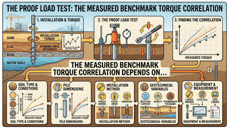
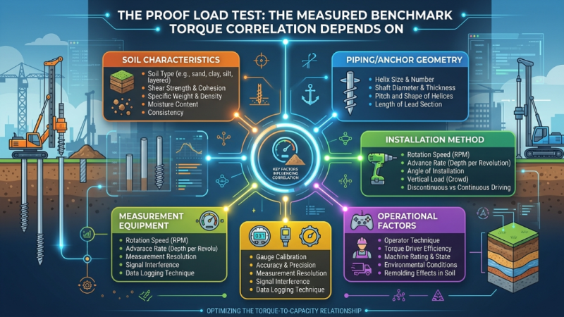
A torque reading predicts capacity. A proof load test measures it. Every field verification method for deep foundations eventually defers to the same authority a pile pushed against the ground under a known load until its movement tells you, without inference, what it will hold. Our earlier field note on torque-to-capacity correlation kept pointing at this test as the higher standard, and for good reason: torque gives you breadth, a reading at every pier, but the static load test gives you depth one real load-deflection curve that no correlation can produce on its own.
This note walks through what a static axial compression test actually measures, how the reaction system and instrumentation are built to keep the number honest, how the result is interpreted against a defined failure criterion, and most usefully for a contractor working the granular soils of Long Island how to back-calculate a site-specific torque correlation factor from the test and carry it into production verification. We stay candid about where a load test gets compromised, and about the judgment call of when the test is worth its cost and when disciplined torque monitoring is enough.
What a Static Load Test Actually Measures
A static load test applies compressive load to a pile in controlled increments and records the resulting axial deflection. The governing procedure is ASTM D1143, Standard Test Methods for Deep Foundation Elements Under Static Axial Compressive Load, which applies to essentially any deep foundation element regardless of how it was installed driven piles, drilled shafts, micropiles, and helical piles alike. The standard is explicit that field tests provide the most reliable relationship between applied load and movement available to the profession. Everything else torque correlation, dynamic methods, theoretical soil-mechanics capacity is an estimate calibrated, directly or indirectly, against this measurement.
Two points about the standard matter in practice. First, it sets minimum requirements; the engineer of record can and often should add procedures to suit the project, and must approve any deviation. Second, a test carried only to the design load proves the pile can carry the design load and nothing more. To learn the pile's actual capacity, the test has to be driven toward a failure load the interpretation criterion can recognize. A test that never approaches failure yields a pass, but no ultimate capacity and no defensible calibration.
The Reaction System: How You Push Against the Ground
To load a pile in compression you need something to push against. On helical work the elegant answer is reaction anchors: install a helical anchor on each side of the test pile, span them with a reaction beam, and use a calibrated hydraulic jack to press the test pile downward while the anchors resist in tension through the beam. Because we are already turning helicals, the reaction system is built from the same hardware we install every day. Where dead weight is preferred over anchors, a kentledge platform can supply the reaction, though the mobilization rarely justifies it on residential and light commercial sites.
The discipline is in the spacing. Reaction anchors set too close to the test pile overlap its zone of soil influence, and their stressed ground stiffens the response the test then measures the reaction system as much as the pile. ASTM D1143 requires a clear distance between the test pile and each reaction anchor large enough that the two do not interact, commonly expressed as a multiple of the largest helix diameter or a fixed minimum distance. Honor that spacing or the curve lies to you.
Instrumentation follows the same logic of independence. Load is measured with a calibrated load cell in series with the jack, not read off jack pressure alone, because ram friction and area assumptions drift the pressure-to-load conversion. Deflection is measured with dial gauges or LVDTs referenced to an independent beam whose supports sit well outside the influence zones of both the test pile and the reaction anchors, with a redundant check a surveyor's level or a wire-and-scale so a single instrument failure does not corrupt the record. A reference beam left in direct sun will grow and shrink enough to swamp the settlements you are trying to read; shade it.
Loading Procedure and What Gets Recorded
ASTM D1143 offers several loading procedures. The quick test loads the pile in small increments on the order of five percent of the anticipated failure load each held for a short fixed interval while deflection is logged, continuing to a failure load or the maximum safe structural load. It is efficient and, in the drained granular soils of the South Shore's glacial outwash, it captures the load-deflection behavior faithfully because there is little time-dependent settlement to wait on. The slow maintained-load procedure uses larger increments held until the settlement rate falls below a threshold, and it earns its extra hours only where creep or consolidation is in play. For code evaluation, ICC-ES AC358 prescribes loading to a multiple of the design load commonly to twice the allowable capacity so the test brackets the working range with margin to spare.
Whatever the procedure, the deliverable is a record: applied load and corresponding net and gross settlement at each increment, the hold time for each, and the plotted load-deflection curve. That curve is the artifact everything else is read from.
Interpreting the Result: The Modified Davisson Criterion
A load-deflection curve does not announce a capacity; a criterion does. The classic Davisson offset limit the elastic compression of the shaft plus 0.15 inch plus the diameter over 120 was developed for driven piles and remains the reference many engineers reach for first. For helical piles, however, capacity develops through bearing of the helix plates, and ICC-ES AC358 adopts a modified criterion suited to that mechanism: failure is the load producing a net (non-elastic) settlement equal to ten percent of the average helix diameter. For a three-helix lead of 8, 10, and 12 inch plates, the average helix diameter is 10 inches, so the criterion is a net settlement of one inch. The load at that point is the measured ultimate capacity.
Using the right criterion is not a formality. Applying a driven-pile offset line to a helical pile, or reading capacity off the gross rather than the net settlement, will hand you a different and indefensible number from the same curve.
Worked Example: Back-Calculating a Site-Specific Kt on Long Island
Here is where the load test and torque monitoring stop being alternatives and become one program. The numbers below are representative and internally consistent an illustration of the method, not a specific job but they are the arithmetic you would run on a real Long Island test pile.
Take a designated 1.75-inch solid square-shaft helical pile installed into the dense glacial outwash to a final average installation torque of 4,500 ft-lb, recorded over the last three feet of advance. The AC358 default torque correlation factor for that shaft is 10 ft¹, which predicts an ultimate capacity of:
Qu(default) = Kt × T = 10 ft¹ × 4,500 ft-lb = 45,000 lb = 45 kip
Now we run a full-scale compression test on that pile against reaction anchors, loading in increments to twice the design allowable. Plotting load against net settlement and applying the Modified Davisson criterion one inch of net settlement for the 10-inch average helix the curve reaches its interpreted ultimate at:
Qm (measured) 49,500 lb = 49.5 kip
Back-calculating the site-specific factor from the pile's own torque log:
Kt(site) = Qm / T = 49,500 lb ÷ 4,500 ft-lb = 11 ft¹
The site supports a Kt of roughly 11 about ten percent above the AC358 default. That gap is real capacity the conservative default would have left in the ground. From here, every production pier on the project can be verified by torque against the calibrated Kt = 11 rather than the generic 10, and the allowable working capacity per pier, at the AC358 factor of safety of 2.0, is set by measured behavior rather than a table:
Q(allowable) = Qm / 2.0 24.75 kip 12.4 tons per pier
The same logic extends to other systems: micropile load testing follows ASTM D1143 identically, though micropile capacity is verified through the grout-to-ground bond rather than a torque correlation, so the test calibrates a bond value instead of a Kt.
Where a Load Test Earns Its Cost and Where Torque Is Enough
A proof test is not free, and the discipline is knowing which projects require one. Load testing earns its cost where loads are significant, where soils are cohesive, layered, or erratic, where the consequences of underperformance are high, where an unproven product or an unusual configuration is in use, or where a building official or the project specification demands it. It also earns its cost, as the worked example shows, when recovering the conservatism baked into default factors turns into fewer or shorter piers.
For lighter residential work in well-characterized granular ground the settling chimney or rear addition on clean South Shore outwash torque monitoring against a sound AC358 or product-specific Kt is generally accepted as adequate verification on its own. The judgment lives in matching the verification to the risk, which is also the judgment behind choosing between helical piers, micropiles, and concrete footings in the first place.
How a Load Test Gets Compromised
A load test is only as trustworthy as its execution. The recurring failures are worth naming.
Reaction anchors set too close. When the reaction anchors' stressed soil overlaps the test pile's, the measured response stiffens and the ultimate reads high. Adequate clear spacing is not optional.
A reference beam that is not independent. Supports inside the influence zone, or an unshaded beam expanding in the sun, introduce movement that has nothing to do with the pile. Support the beam well outside the influence zones and shade it, and keep a redundant displacement measurement running.
Trusting jack pressure instead of a calibrated load cell. Ram friction and effective-area error make hydraulic pressure an unreliable stand-in for load. A calibrated cell in series is the number that counts.
Loading at the wrong rate. Too fast in a creep-sensitive soil masks time-dependent settlement; too slow in clean sand wastes a day for no added information. Match the procedure to the ground.
Stopping short of the criterion. A test halted at the design load proves adequacy but yields no ultimate and no calibration. If the goal is a site-specific Kt, the test has to reach the failure criterion.
Eccentric or out-of-plumb loading. A jack line off the pile axis induces bending that reads as false stiffness or premature yield. Seat and align before the first increment.
Where Torque Verification Supplements but Does Not Replace the Load Test
None of this makes the two methods competitors. A load test measures what one specific pile does under a controlled load, interpreted against a defined criterion depth. Torque correlation gives a fast, non-destructive capacity estimate at every pier at no added mobilization breadth. The strongest field programs use them together in a deliberate sequence: on any project where loads are significant, soils are cohesive or erratic, or consequences are high, run a full-scale load test early on a designated or sacrificial pile, back-calculate the site-specific Kt from that result, then use torque monitoring to verify every remaining pier against the calibrated value. You get the rigor of a measured load-deflection curve and the wall-to-wall coverage of torque verification in one program. On lighter residential work in well-understood granular ground, torque against a sound Kt stands on its own. Knowing which project is which is the engineering.
What a Defensible Load Test Record Documents
The value of a proof test is realized only if the record can stand on its own years later. A complete record documents the test pile's identification and location, its shaft and helix configuration, and its full installation torque log; the reaction system and the clear spacing to the reaction anchors; calibration certificates for the jack, load cell, and displacement instruments; the loading schedule with increments and hold times; the measured load-deflection data and the plotted curve; the interpreted ultimate capacity and the criterion used to define it; the back-calculated site-specific Kt where one is derived; environmental conditions; and the engineer of record's interpretation. That package is what lets a structural engineer, a building official, or a future owner see that the foundation was measured, not assumed and it is what ties every torque-verified production pier back to a real, tested number.
Final Thoughts
Torque-to-capacity correlation is the most practical field verification tool in deep foundations because it reads capacity at every pier from the same soil resistance that will carry the structure. The proof load test is the reason that reading can be trusted: it is the measured benchmark the correlation is calibrated against, the one method that produces a real load-deflection curve and a defensible ultimate. Used together the load test to calibrate, torque to verify they give a foundation program both depth and breadth, and they let a contractor hand the client not a promise but a record. That is the difference between a pile you hope will hold and one you have documented will.
Selected References
- ASTM D1143/D1143M-20, Standard Test Methods for Deep Foundation Elements Under Static Axial Compressive Load. ASTM International.
- ICC-ES AC358, Acceptance Criteria for Helical Pile Systems and Devices. ICC Evaluation Service.
- Davisson, M. T. (1972). High Capacity Piles. Proceedings, Soil Mechanics Lecture Series on Innovations in Foundation Construction, ASCE Illinois Section, Chicago, pp. 81112.
- Perko, H. A. (2009). Helical Piles: A Practical Guide to Design and Installation. John Wiley and Sons.
- Hoyt, R. M., and Clemence, S. P. (1989). Uplift Capacity of Helical Anchors in Soil. Proc. 12th International Conference on Soil Mechanics and Foundation Engineering, Rio de Janeiro, Vol. 2, pp. 10191022.
Categories
Pile Foundations, Deep Foundations, Soil Structure Interaction, Soil Dynamics In-Situ
Keywords
pile load testing, pile foundations