
Published: 14 August 2026
A PLAXIS 3D numerical study of under-reamed 'winged' piles in sandy soil has found that adding a wing near the pile tip can cut uplift-induced settlement by up to 95% compared with a conventional straight-shaft pile at the same applied load.
The study, presented at ICSMGE 2026 by Maher Jebur, Firas Ghrairi, Adnan Qahtan and Mahdi Karkush of the University of Baghdad, Khawla Aljuari of the University of Mosul, Askar Zhussupbekov and Gulnaz Zhairbayeva of L.N. Gumilyov Eurasian National University in Astana, and Issakulov Abilkhair of K. Zhubanov Aktobe Regional University, used PLAXIS 3D to analyse the pullout performance of winged piles in sandy soil, using soil properties taken from Al-Muthanna Governorate in southern Iraq. Winged, or under-reamed, piles carry one or more enlarged 'wing' sections along the shaft to mobilise additional soil resistance, and are used in structures that experience tensile or pullout forces, including transmission towers, bridge abutments and submerged platforms.
Modelling the Pile-Soil Interface in PLAXIS 3D
The PLAXIS 3D model represented a pile of 0.45 m diameter and 12 m length with a wing diameter of 1.0 m, tested with the wing placed at four different depths along the shaft, measured from the pile head: L, 0.75L, 0.5L and 0.25L, and compared against a conventional uniform straight-shaft pile with no wing. The sandy soil was modelled using the Mohr-Coulomb constitutive model to represent its shear strength and dilatancy, while the pile itself was modelled as a linear elastic material. Interface elements were added around the periphery of the pile and its wing to reproduce the frictional and adhesive contact between soil and pile, and the model domain's lateral and bottom boundaries were extended well away from the pile to avoid boundary effects on the computed stresses and deformations. PLAXIS 3D discretised the domain with 10-node tetrahedral elements, and a mesh sensitivity analysis found that a global 'Fine' coarseness setting gave an adequate balance of accuracy and computational efficiency.
The loading sequence was run in PLAXIS 3D as four stages: an initial K0 procedure to establish in-situ geostatic stresses, deactivation of the soil volume within the pile cluster to represent borehole formation or pile installation, activation of the pile and wing structure together with the interface elements to simulate soil-pile interaction, and finally an applied axial displacement at the pile head to simulate the pullout condition, with reaction forces recorded to determine uplift capacity. Before running the winged-pile cases, the authors validated the modelling approach in PLAXIS 3D against published experimental pullout test data for a 4.5 m under-reamed pile, reporting a high degree of correlation between the simulated and measured load-displacement response, which they state confirmed the constitutive models, interface parameters and boundary condition assumptions used.
PLAXIS Contours Show the Wing's 'Bulb Effect'
Running the calibrated model across the five pile configurations, PLAXIS 3D's uplift displacement contours showed the conventional uniform pile mobilising a narrow column of soil directly around the shaft, with an uplift displacement of about 0.20 m under the applied load.
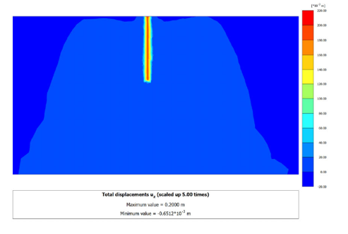
PLAXIS 3D vertical displacement distribution for the conventional pile of uniform cross-sectional area, showing a maximum displacement of 0.20 m.
By contrast, the winged pile configurations mobilised a distinctly bulb-shaped mass of soil around the wing, with recorded displacements of 0.009 m for the wing positioned at L, 0.013 m at 0.75L, 0.020 m at 0.5L, and 0.051 m at 0.25L. The pile with the wing at position L, which produced the smallest displacement of any configuration, achieved an approximately 95% increase in uplift capacity relative to the conventional pile at the same 20 mm vertical displacement, the largest improvement among the configurations tested.
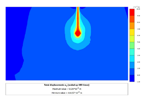
PLAXIS 3D uplift displacement distribution for the pile with its wing positioned at L, showing a maximum displacement of 9.539 x 10⁻³ m, a bulb-shaped zone of mobilised soil around the wing.
The authors attribute this behaviour to the wing inducing a 'bulb effect' in the surrounding soil mass that prevents the formation of potential slip planes and instead mobilises a larger volume of soil during uplift, increasing both the contact area between pile and soil and the skin friction that can be mobilised along the shaft. The PLAXIS contours also show that the position of the wing changes the geometry of the mobilised soil mass and the depth at which maximum soil deformation occurs, which the authors link to the formation of different potential shear planes for each wing position.
The authors conclude that placing wings on a pile considerably reduces uplift-induced settlement, by between 74% and 95% depending on the pile's geometry and the embedment depth of the wing, and that a properly designed and positioned wing can significantly improve pullout capacity and soil-pile interaction relative to a conventional, non-winged pile in sandy soil.
Categories
Pile Foundations, Deep Foundations, Finite Element / Finite Difference
Keywords
PLAXIS3D, Seequent, Bentley, ISSMGE